Generating Complex Waveforms Using Siglent’s Combine Function on the X-Series Dual-Channel Generators
October 24, 2017
It is common in engineering to combine two signals into one, such as superimposing noise on a sinusoid to simulate a desired signal containing undesired noise, or testing the OIP3 (Output 3rd Order Intercept Point) of an amplifier by generating a two-tone signal. The Siglent X series dual-channel waveform generators (SDG1000X, SDG2000X) can accomplish this type of waveform using either of two methods. We will explain both methods below.
Method #1: Combining Externally
As shown in Figure 1, outputs of the two channels are shorted together by a T-connector, and then connected to the load. The resulting output from the T-Connector will be CH1 & CH2 combined.
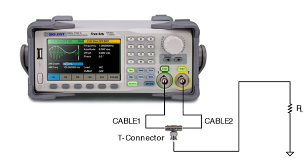
Figure 1 Combining the 2 channels from External
In general, the generator has a 50 Ω output impedance so there is no problem with tying the two outputs together externally. All of Siglent’s waveform generators meet this requirement. Below is the explanation based on circuit analysis methodology.
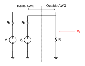
Mark the output voltage of channel 1 as V1, output voltage of channel 2 as V2, output impedance of each channel as Rs, load impedance as RL, and the voltage dropped across RL as Vo, as shown in the figure below.
According to the superposition principle of linear circuits, Vo can be decombined into Vo1 and Vo2, which are respectively the equivalent voltage on the load generated by V1 and V2, as shown in the figure below. The calculation for Vo1 , Vo2 and Vo are shown in formula (1).
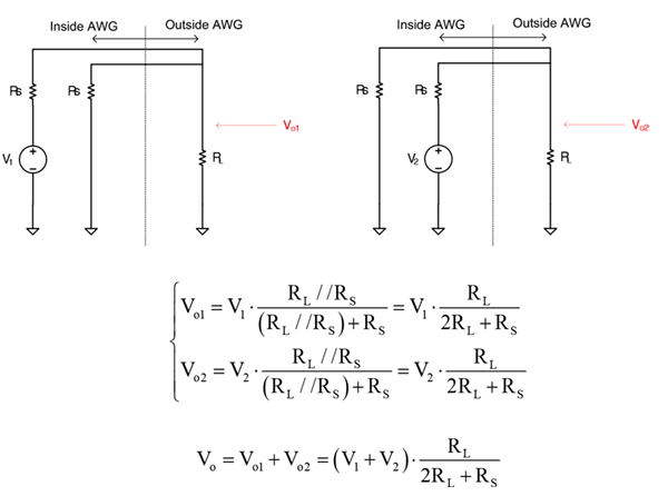
Generally, the output impedance, Rs, is 50 Ω, so formula (1) can be rewritten as:

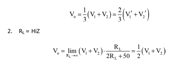
The most common two load conditions are discussed below:

Attention should be paid that V1 and V2 are two times that of the set value (V1’, V2’) by user when the channel load of the channel is set as 50 Ω. Therefore, if Vo is represented with the set value of both channels, formula (2) can be rewritten as:
Method #2: Combining Internally
Method #1 has some limitations:
1. Per formula , Vo isn’t the simple sum of the outputs of the two channels. A cofficient which is relevant to RL should be multiplied on the sum. Therefore, to get a correct Vo, users should caculate V1 and V2 according to their own application.
2. Method #1 only applies to the signal with low frequency. The cable 1 or cable 2 in Figure 1 is a stub on the signal path for the channel which is not conneted to it. (i.e. For channel 2, cable 1 is a stub, and vice vesa). As we know, a stub in a signal path will cause refletion which causes signal integraty issues. This kind of issue is not obvious when working with low frequencies but cannot be ignored at higher frequencies.
3. Requires several external components, including two BNC cables and a T connector, at a minimum.
In view of the problems listed above, Siglent’s SDG1000X and SDG2000X series dual-channel have added the Waveform Combine function to the internal operation of the generator. With this added feature, combining waveforms is a simple process.
Press the Utility button on the front panel, and choose Output Setup, then Wave Combine.The user interface of the Waveform Combine function will be shown, as in Figure 2:
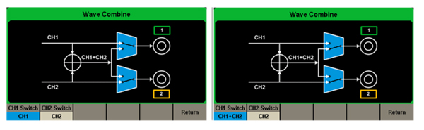
Figure 2 User Interface of the Waveform Combine Feature
By default, channel 1 outputs the waveform set by “CH1” interface, channel 2 outputs the waveform set by “CH2” interface. That is to say, both the channels will not output the combined waveform, see Figure 2 (a). As long as the CH1 is set to “CH1+CH2”, the combined waveform CH1+CH2 is output from channel 1, as shown in Figure 2 (b).
The X series waveform generators can combine the waveforms from the two channels internally. As a result, only one external cable is necessary, saving external accessories and guaranteeing signal integrity. Meanwhile, the other channel can output its original waveform or combined waveform.
The combined waveform of X series generators isn’t simply pre-calculating the sum of the two channels’ waveform data, then storing to the lookup table and finally outputting it via DDS. It’s a real-time calculation of the data. The benefits include:
1. The combined waveform is generated in real time, without the need to recalculate and load the waveform data every time the setting of waveform is changed.
2. To superpose a real non-periodic random noise is possible, which is definitely superior to the pre-calculated period noise stored in DDS.
3. All the EasyPulse and TrueArb waveforms generated by the X series can be superposed.
All the modulation, sweep and burst signals can be superposed.
Application Examples
Example #1
This is a popular application. To output a sinusoid polluted by noise, to verify the filtering or noise performance of some systems.
As shown in Figure 3, channel 1 is set to a sine wave with 1 kHz frequency, and channel 2 is set to noise. With the methods above, we can get a sinusoid with noise.
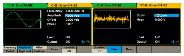
Figure 3 Setup of the Waveform Generator in Example 1
Figure 4 and Figure 5 respectively show the output waveforms generated externally (Method 1) and internally (Method 2). Combined results are consistent. Alternately, we measured the combined waveform using an oscilloscope with 1 MΩ input impedance (Can be approximated regarded as Hi Z). According to formula , the amplitude of the combined waveform using Method #1 is half of the set value. This does not occur using Method 2.
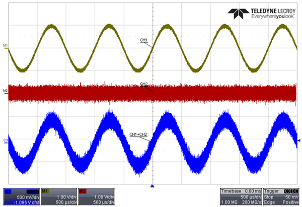
Figure 4 Sinusoid with Noise from Method #1
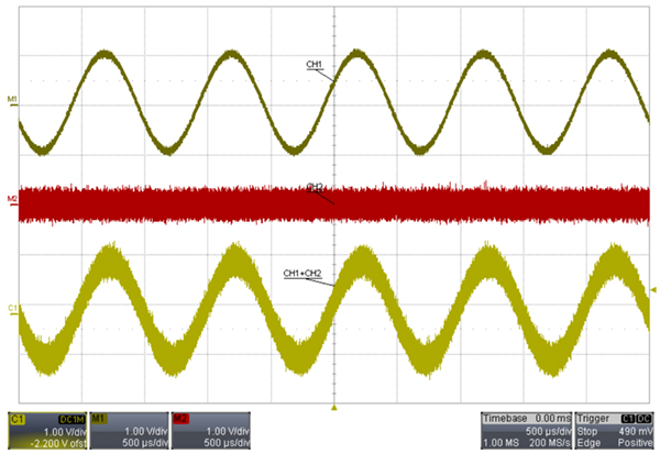
Figure 5 Sinusoid with Noise from Method #2
Example #2
The following is an example of how to generate a two-tone signal.
As shown in Figure 6, channel 1 is set to sinusoid with 1 kHz frequency, and channel 2 is set to sinusoid with 3 kHz frequency. Figure 7 and Figure 8 respectively show waveforms generated externally and internally. As before, the combined waveform from the two methods are consistent as expected, but the amplitude of the waveform created by external combination is half of the set value.
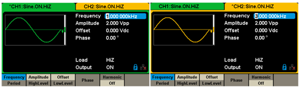
Figure 6 Setup of the Waveform Generator in Example 2
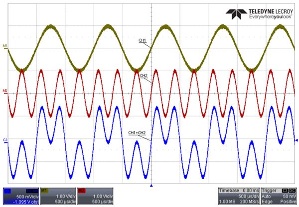
Figure 7 Two-tone from Method #1
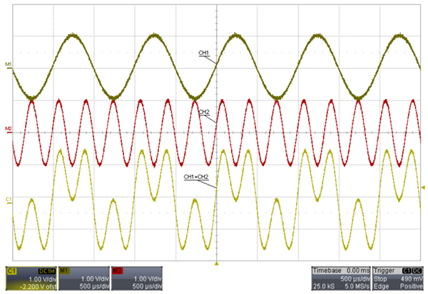
Figure 8 Two-tone from Method #2
Conclusion
The X series dual-channel waveform generators from Siglent (SDG1000X, SDG2000X) are capable of combining the outputs of the two channels. And the internal combining method has the advantage of the real-time ability of superposing random noise, modulation signals, sweep signals, burst signals, EasyPulse waveforms and TrueArb waveforms. From the above, the X series dual-channel waveform generators provide users a new better way to generate complex waveforms accurately and conveniently.
All released versions of the SDG1000X support the function of Waveform Combination. For the SDG2000X, the releases after 2.01.01.21R2 (included) support it. Users of older SDG2000Xs can get the function free by upgrading the firmware for their X series generators.